Review of thin steel plate double side milling machine
Hou Bin Ma Rungang Li Wubin Dang Jiqiang Xu Dali
ã€Abstract】 This paper introduces the composition, technical principle, selection of basic parameters, main technical indicators and key technologies and solutions of thin steel double-sided milling machine. The production operation shows that the machine tool is stable, safe and reliable, and has obvious economic benefits. It can completely replace imported products for reference and reference by technicians in this industry.
[Keywords] thin steel drum, double-sided milling, milling accuracy, milling power head, visibility fine-tuning
introduction
For the steel drum industry and the container manufacturing industry, the use of coated steel sheets for raw material production, the machine tool uses the milling method, the coated thin steel sheet (the most widely used in China is the galvanized sheet, the thickness is 0.9mm~1.5 Mm) The upper and lower edges of the two edges are processed from 8mm to 14mm, eliminating the coating layer at the seam welding joint, providing a smooth surface for the next process, seam welding, to solve the industrial production of coated sheets (green sheets) Steel drums and containers have been a bottleneck for industry players.
1 Machine component
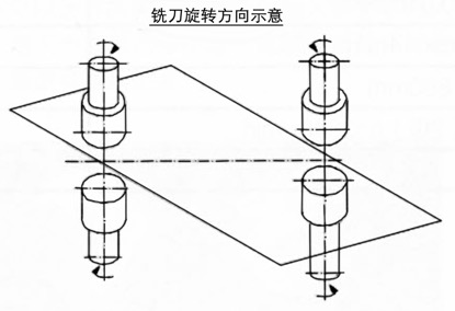
The edge milling machine uses a loading robot to put the pre-milled sheet into the loading table, and conveys it through the feeding device. Through two pairs of upper and lower, four milling power heads, the upper and lower sides and the opposite sides of the sheet are simultaneously milled.
The figure below shows the milling schematic.
2 Technical problems involved in machine tools
(1) Milling accuracy: the thickness of the steel plate to be milled is 1.5mm~0.9mm, and each steel plate needs to be milled at both ends in the direction of the width of the plate (≤1000mm) and the width of the upper and lower milling is 8mm~14mm, thickness (milling layer ) 0.05mm ~ 0.08mm, how to ensure the milling edge accuracy (milling edge accuracy seriously affects the quality of the steel drum), and control the milling accuracy within a certain error range, this is one of the key technologies.
(2) Preventing the occurrence of cornering: how to prevent the plate from being shaken or upturned during the milling process, and tearing the steel plate when the cutter is cut or cut, and the cornering phenomenon occurs.
(3) Realize the fine adjustment of the milling power head to ensure the speed regulation accuracy.
(4) To realize the production of various products with different plate widths (1200mm~1900mm) and different material thicknesses (0.9mm~1.5mm).
(5) to achieve cooling of the milling head and reduce the wear of the blade,
(6) Reasonably set the offset angle of the milling power head.
3 Selection of main technical parameters
3.1 Calculation of milling force
The milling process can be divided into three phases. The milling cutter of the milling head is in contact with the steel sheet material in the first stage of elastic deformation. The milling cutter continues to cut into the steel plate, and the steel sheet material enters the second stage of plastic deformation. As the cutting force increases, the plastic deformation increases, and the grain of the material slips. When the cutting force reaches the strength limit of the steel plate, the material of the material to be cut is cracked, that is, enters the third stage, and finally cuts. from. The cutting force is divided into three component forces, namely tangential force, radial force and axial force. The experimental radial force can not be greater than 2 times of the tangential force. The larger radial force will cause the elastic deformation of the process system consisting of the frame, the steel plate and the milling head, thus affecting the milling precision. How to reduce the radial force in the design of the milling head tool is one of the considerations.
3.2 Milling power head installation offset angle
The central axis of the milling head has an offset angle from the feed direction of the steel plate. This offset angle setting has three functions: one is to improve the stability of the milling edge; the other is to facilitate the feeding of the steel plate; the third is the need for milling the edge shape. The steel drum is made of thin steel plate with poor rigidity, and the milling force of the milling edge is large. The conveying steel plate is only fed by the two rollers of the feeding device. If there is no offset angle, like the plane milling, the milling force is due to the milling force. Larger ones will cause the steel plate to bow and the conveying resistance is large. Properly setting the offset angle milling force can be decomposed into two mutually perpendicular component forces. The component force along the direction of the steel plate feeding direction is received by the guide plate. The component force in the direction of the vertical steel plate is symmetrically set on both sides. Just right and left balance, so it will be much more stable to carry together. The setting of the offset angle of the milling power head is also convenient for feeding the steel plate. Therefore, the choice of the offset angle must be comprehensively considered according to the properties of the steel plate, the conveying capacity and the width of the milling edge, and reasonable selection.
4 overall technical solutions
The machine tool automatically feeds the galvanized sheet into the loading table of the machine tool by the loading robot. The machine tool is provided with a feeding device, and the feeding device comprises a front nip roll, a rear nip roll and a guide plate. Both the front nip roller and the rear nip roller are fixed on the fuselage frame body and connected to the feeding drive motor through a transmission device, and the guide plates are disposed at both side edges of the fuselage frame body. The front part of the front nip roll is provided with a discharge table, and the rear nip roll has a loading table at the rear. Two pairs of milling power heads are arranged between the front nip roll and the rear nip roll, and the milling power head is disposed close to the guide plate. A plate pressing device is arranged on the body frame of the milling device, and a linear card slot is arranged on the body frame between the front nip roller and the rear nip roller, and the milling power head is fixed in the linear card slot and can be Adjust the lateral spacing between the milling heads at both ends along the linear slot as needed. The milling power head is provided with a vertical feed device, and the feed handle can adjust the distance between the milling cutter and the plate to meet different milling depths. A variety of different sizes of steel drum sheets can be machined by adjusting the distance between the milling power heads. A displacement measuring device is arranged on the axial feed device between the milling power head and the milling cutter to achieve precise adjustment of the milling feed.
Table 1
name
unit
Number setting
Remarks
1
Automatic loading robot
set
1
2
Feeding unit
set
1
3
Milling power head unit
set
4
4
Pressing part
set
1
5
bed frame
set
1
6
Air cooling device for milling cutter
set
1
7
Milling collection system
set
2
8
Sliding roll assembly
set
1
9
Milling head adjustment detection system
set
4
Four-way precision displacement measuring instrument
10
Electronic control system
set
1
5 innovation points
(1) The milling edge process is a new process innovation compared to the chemical method and the edging process, and realizes the connection with the fully automatic production line, which is the first in China.
(2) The steel plate conveying automatic shifting mechanism is designed to prevent the steel plate from being torn when the cutter is cut or cut, and the cornering phenomenon occurs.
(3) The power head offset angle device and the pressing device for preventing the plate from being shaken or upturned during the milling process.
(4) 45° large rake angle, four-sided edge milling cutter with small milling load, ensuring high-speed and stable milling quality.
(5) It can adapt to the production of plates with different thicknesses and different widths.
(6) There is a four-way displacement measuring system, which shows the adjustment of the milling head with visibility, and realizes the precise adjustment of the milling head to adapt to the production of different thickness plates.
6 Main technical indicators (Table 2)
Table 2
name
parameter
Remarks
1
Milling edge width
8mm~14mm
2
Milling depth
0.06mm~0.08mm
Adjustable
3
Processing range (board scale)
500mm~1900mm
Adjustable
4
Adjustment accuracy
0.05mm / circle
5
measurement accuracy
0.01mm
6
Productivity
3m/min~4m/min
7
Feeding height
890mm
8
Motor Power
Milling head motor
4×1.1kw (level 2) n=2840n/min
Feed motor
3kw
Frequency
Conclusion
This product has been successfully applied in Guangdong, Fujian, Jiangsu, etc. in 2012. Since it was put into production, it is stable, reliable, noise-free and dust-free, and easy to connect. It is a practical method for producing steel drums and containers with coated steel plates. In place of the necessary settings for the edging machine, the economic benefits are remarkable. Practice has proved that the development of this machine tool is successful and has a good promotion value; the innovative design concept adopted is worthy of peer reference. In the future, it is necessary to strengthen research and develop a high-speed edge milling machine with a productivity of more than 8 pieces per minute to meet the needs of users. (This article was originally published in "China Packaging Industry")
Baking Paper,Baking Paper Liner,Oven Baking Paper,Baking Glassin Paper
NINGBO FAVORED COMMODITY CO.,LTD , https://www.favored-top.com